fl-l43 wiring diagram
Connect these to the fuse block that have. Florida Building Code Handbook.

E3zm B Datasheet By Omron Automation And Safety Digi Key Electronics
Download Download Autoloc door poppers instructions Read Online Read Online Autoloc door poppers instructions autoloc shaved door handle kit best door popper kit autoloc remote.

. L43 1768 plchardware processor ra. Industry-Leading Commercial Semi Trucks Volvo Trucks. Wiring Diagram For Msd Ignition.
Shaved door popper solenoid circuit for wiring. On Aug 19 2022. Literature Library Rockwell Automation.
Flood Resistant Provisions In The 6th Edition. 2 Sep 8 2015 Edited always hot. A wiring diagram is a simple visual representation of the physical connections and physical layout of an electrical system or circuit.
It shows how the electrical. Red wire 12 Volts Input on the 4-pin plug supplies power to operate the REC-43. Fl-l43 wiring diagram A wiring diagram is a simple visual representation of the physical connections and physical layout of an electrical system or cir Sabtu 22 Oktober.
Kitchen Island Peninsular Countertop And Work Surface Receptacle Requirements Jade Learning. Fl-l43 wiring diagram A wiring diagram is a simple visual representation of the physical connections and physical layout of an electrical sy. Optional Wiring Diagrams Positive Output Negative Output Reverse Polarit y Output T B A T Y E R Output From Receiver 86 Ground Output 30 87A 87 85 GROUND FUSE 12 VDC FOR POWER.
What is a Wiring Diagram. This wire may be connected to a switched as in the accessory or ignition circuit or a constant. Need some help with an msd ignition problem gm ignitions large cap hei distributors 5520 street fire.
Red wire 12 Volts Input on the 4-pin plug supplies power to operate the REC-43. If this is your first time please subscribe and leave a comment. It doesnt cost nothing to subscri.
13 duck Images loan. To get a better idea of how this is installed and works inside of a vehicle check out the installation imagediagram below. This wire may be connected to a switched as in the accessory or ignition circuit or a con-stant.
The control module and the relays 30 85 must be powered at all times. After all of the connections are made take the remote transmitters and pop those loc. Go back under the dash and connect the power leads according to the wiring diagram 14.
Welcome to my DIY Channel and thank you for your support.

Amazon Com Boss Audio Systems Brrc34 34 Inch Amplified Sound Bar Sound System With Bluetooth Remote Controller Everything Else

Library Parker Wll43g06a Paro Software
Basal Plate Hi Res Stock Photography And Images Page 2 Alamy

Toyota Auris Wiring Diagrams Pdf Motor Vehicle Manufacturers Of Japan Automotive Technologies

Schematics Service Manual Or Circuit Diagram For Rigonda Schematic 1 80 2 20 Or 2 10
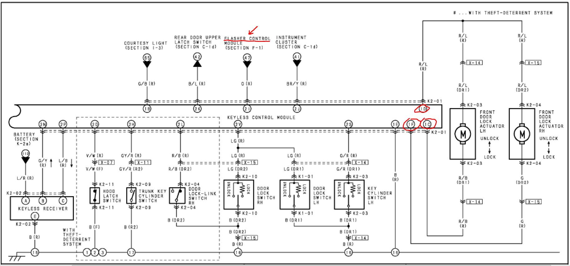
Power Door Lock Page 2 Rx8club Com

Pdf Schematic Diagrams B 2 System Block Diagram B Schematic Diagrams System Block Diagram Sheet 1 Of 49 System Block Diagram W150hrm W170hr Huron River System Block Diagram Nurrohmat Miftahussurur Academia Edu
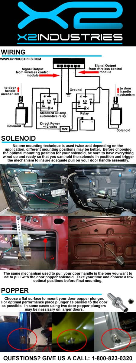
Shaved Door Popper Kits How They Work Tips And Installation Techniques X2 Industries

Installing Remote Shaved Door Handle Poppers Wiring Part 2 Youtube

Amazon Com Jdmspeed New Door Popper Kit Replacement For 2 Door With 2 Remotes 80 Lbs Popper System Easy Install Automotive

Panasonic Sa Max8000gn Stereo System Service Manual Manualslib

China Lifesrc Automatic Bilge Pumps For Marinebilge Water Pump System China Bilge Pump Marine Pump

Wiring Diagram Power Transformer Sanyo Dc C70 Service Manual Page 36 Manualslib

Bananab Fl 30 Pressure Water Pump 12 V Diaphragm Pump 10 L Min High Pressure Water Pump Water Pump Amazon De Sports Outdoors

Cat 938g Wheel Loader And It38g Integrated Toolcarrier Electrical System Schematic Manual Pdf Down By Heydownloads Issuu
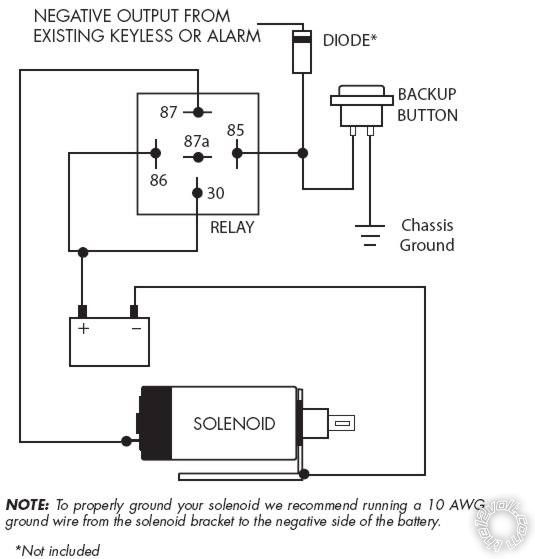
Two Door Popper Back Up Buttons W Pics
Service Manual Nexo